Components
COMPONENTS
ILLUSTRATION
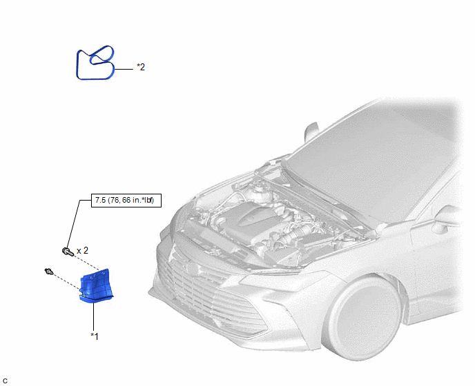
|
*1 | FRONT FENDER APRON SEAL RH |
*2 | V-RIBBED BELT |
 |
N*m (kgf*cm, ft.*lbf): Specified torque |
- | - |
Installation
INSTALLATION
PROCEDURE
1. INSTALL V-RIBBED BELT
HINT:
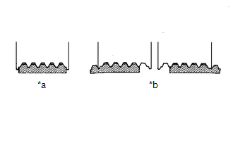
When reusing the V-ribbed belt, check the ribs and back of the V-ribbed belt for wear and cracks. If wear or a crack that reaches the core (at more than 1 point) is found, replace the V-ribbed belt.
| (a) Install the V-ribbed belt. NOTICE:
|
|
(b) Turn the V-ribbed belt tensioner assembly counterclockwise and remove the 5 mm hexagon wrench.
| (c) After installing the V-ribbed belt, check that it fits properly in the ribbed grooves. Confirm that the V-ribbed belt has not slipped out of the grooves on the bottom of the pulley by hand. |
|
2. INSTALL FRONT FENDER APRON SEAL RH
Click here

3. INSTALL FRONT WHEEL RH
Click here
Removal
REMOVAL
PROCEDURE
1. REMOVE FRONT WHEEL RH
Click here 
2. REMOVE FRONT FENDER APRON SEAL RH
Click here
3. REMOVE V-RIBBED BELT
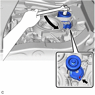
| (a) Release the V-ribbed belt tension by turning the V-ribbed belt tensioner assembly counterclockwise. |
|
(b) Turn the V-ribbed belt tensioner assembly counterclockwise to align its holes, and then insert a 5 mm hexagon wrench to secure the V-ribbed belt tensioner assembly.
(c) Remove the V-ribbed belt from the V-ribbed belt tensioner assembly.
Toyota Avalon (XX50) 2019-2022 Service & Repair Manual > Exterior Panels / Trim: Front Door Window Frame Moulding
Components COMPONENTS ILLUSTRATION *1 FRONT DOOR GLASS RUN *2 FRONT DOOR LOWER FRAME BRACKET GARNISH *3 FRONT DOOR PANEL PROTECTOR *4 FRONT DOOR UPPER WINDOW FRAME MOULDING *5 FRONT DOOR WEATHERSTRIP *6 FRONT DOOR WINDOW FRAME MOULDING (CENTER PILLAR SIDE) *7 RIVET - - в—Џ Non-reusable part - - Inst ...