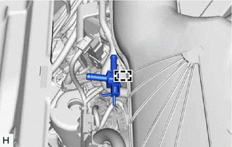
Toyota Avalon (XX50): Brake Vacuum Hose(for Gasoline Model)
Components
COMPONENTS
ILLUSTRATION
|
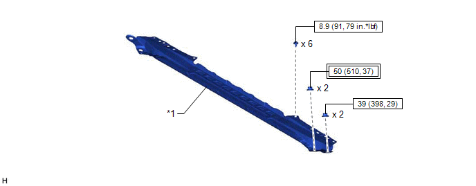
*1 | FRONT CENTER UPPER SUSPENSION BRACE SUB-ASSEMBLY |
- | - |
 |
Tightening torque for "Major areas involving basic vehicle performance such as moving/turning/stopping" : N*m (kgf*cm, ft.*lbf) |
 |
N*m (kgf*cm, ft.*lbf): Specified torque |
ILLUSTRATION
|
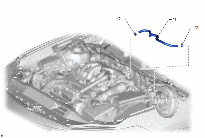
*1 | UNION TO CHECK VALVE HOSE |
*2 | CLIP |
ILLUSTRATION
|
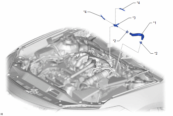
*1 | AIR TUBE |
*2 | CLIP |
|
*3 | AIR DELIVERY WAY |
*4 | VACUUM TRANSMITTING HOSE ASSEMBLY |
Installation
INSTALLATION
PROCEDURE
1. INSTALL AIR TUBE
| (a) Engage the clamp to install the air delivery way to the intake air surge tank assembly. |
|
(b) Install the 2 clips to the air tube.
| (c) Connect the air tube to the air delivery way, and slide the clip to secure it.
NOTICE:
- Make sure to position the paint mark of the air tube as shown in the illustration.
- Make sure that the tabs of the clip are aligned as shown in the illustration.
| |
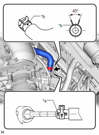
| (d) Connect the air tube to the vacuum pump assembly, and slide the clip to secure it.
NOTICE:
- Make sure to position the paint mark of the air tube as shown in the illustration.
- Make sure that the tabs of the clip are aligned as shown in the illustration.
|
 |
|
*a | Paint Mark | |
*b | Dot Paint | | |
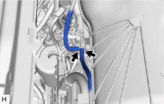
| (e) Connect the 2 vacuum transmitting hose assemblies to the air delivery way. |
|
2. INSTALL UNION TO CHECK VALVE HOSE
(a) Install the 2 clips to the union to check valve hose.
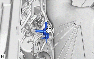
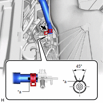
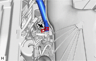
| (b) Connect the union to check valve hose to the air delivery way, and slide the clip to secure it.
NOTICE:
- When connecting the union to check valve hose, face the paint mark up.
- Make sure that the tabs of the clip are facing upward.
| |
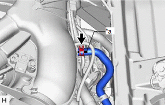
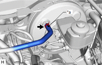
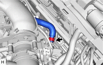
| (c) Connect the union to check valve hose to the brake booster assembly, and slide the clip to secure it.
NOTICE:
- When connecting the union to check valve hose, face the paint mark up.
- Make sure that the tabs of the clip are facing upward.
| |
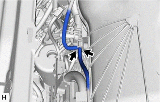
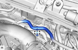
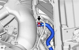
| (d) Engage the clamp to install the union to check valve hose to the air tube. |
|
3. INSTALL FRONT CENTER UPPER SUSPENSION BRACE SUB-ASSEMBLY
Click here

4. INSTALL COWL TOP VENTILATOR LOUVER SUB-ASSEMBLY
Click here 
Removal
REMOVAL
PROCEDURE
1. REMOVE COWL TOP VENTILATOR LOUVER SUB-ASSEMBLY
Click here 
2. REMOVE FRONT CENTER UPPER SUSPENSION BRACE SUB-ASSEMBLY
Click here 
3. REMOVE UNION TO CHECK VALVE HOSE
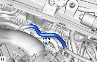
| (a) Disengage the clamp to separate the union to check valve hose from the air tube. |
|
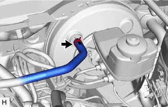
| (b) Slide the clip and disconnect the union to check valve hose from the brake booster assembly. |
|
| (c) Slide the clip and disconnect the union to check valve hose from the air delivery way. |
|
(d) Remove the 2 clips from the union to check valve hose.
4. REMOVE AIR TUBE
| (a) Disconnect the 2 vacuum transmitting hose assemblies from the air delivery way. |
|
| (b) Slide the clip and disconnect the air tube from the vacuum pump assembly. |
|
| (c) Slide the clip and disconnect the air tube from the air delivery way. |
|
(d) Remove the 2 clips from the air tube.
| (e) Disengage the clamp to remove the air delivery way from the intake air surge tank assembly. |
|


